What Is a Pressure Regulator and How Does It Work?
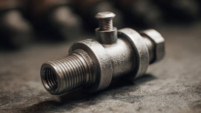
A pressure regulator may look like a compact metal fitting, but it performs a demanding job: it reduces a variable inlet pressure and helps maintain a steadier outlet pressure as flow changes. Inside, a spring, diaphragm, and valve respond to pressure shifts. The details matter. A regulator selected for the wrong flow range can cause outlet pressure to sag, fluctuate, or rise beyond the intended setting.
The U.S. Department of Energy’s Improving Compressed Air System Performance: A Sourcebook for Industry identifies compressed air as a significant manufacturing energy user, commonly accounting for about 10% of industrial electricity use. That figure describes compressed-air systems, not regulators alone, but it shows why pressure control deserves careful attention. In a plant, even a small pressure mismatch can affect tools, instruments, and production equipment across a long line.
Instrumentation authority Bela G. Liptak, editor of the Instrument Engineers’ Handbook, is a relevant technical reference for understanding measurement and control. I cannot verify a verbatim quotation from him specifically about pressure regulators, so I won’t present invented words as his. A practical takeaway consistent with instrumentation engineering is this: “Good pressure control starts with the right measurement, sizing, and operating conditions.” Treat that as a summary, not a direct quotation. In the sections ahead, we’ll examine regulator components, operating principles, common types, and selection factors. The goal is practical understanding—not assuming that one regulator suits every system.
Pressure Regulator Fundamentals: 1 bar Equals 100 kPa
What Is a Pressure Regulator and How Does It Work?
Pressure Regulator Fundamentals: 1 bar Equals 100 kPa
A pressure regulator reduces higher inlet pressure and helps maintain a chosen downstream pressure. Inside, a spring and diaphragm respond to pressure changes, adjusting a valve opening. The result is steadier flow for equipment designed to operate within a specific pressure range. A regulator does not make pressure unlimited or remove the need for suitable system components.
The unit conversion is simple: 1 bar equals 100 kilopascals (kPa). So a reading of 2.5 bar equals 250 kPa. Check whether a gauge shows relative pressure, often marked “barg,” or absolute pressure, marked “bara.” At roughly sea level, 1 barg is about 2 bar absolute. That distinction matters when comparing readings or following equipment specifications. Real systems can fluctuate, especially when flow demand changes; a regulator has operating limits.
Tips: Read the regulator’s scale and equipment instructions before adjusting it. Change settings gradually, then check the downstream gauge while the system is operating. If readings drift or pressure behaves unexpectedly, stop and inspect the setup with a qualified technician. Small gauges can be hard to read.
What Is a Pressure Regulator and How Does It Work? - Pressure Regulator Fundamentals: 1 bar Equals 100 kPa
| Topic |
Parameter |
Value or Component |
Description |
| Pressure Unit Conversions |
Bar to kilopascals |
1 bar = 100 kPa |
One bar is defined as 100,000 pascals, or 100 kilopascals. |
| Bar to pascals |
1 bar = 100,000 Pa |
Pa (pascal) is the SI unit of pressure. |
| Bar to pounds per square inch |
1 bar ≈ 14.5038 psi |
The displayed value is rounded; psi means pounds per square inch. |
| Kilopascals to bar |
1 kPa = 0.01 bar |
Divide a pressure in kilopascals by 100 to express it in bar. |
| Atmosphere to bar |
1 atm = 1.01325 bar |
A standard atmosphere is slightly greater than one bar. |
| Example conversion |
300 kPa = 3 bar |
Divide 300 kPa by 100 kPa per bar. |
| Regulator Fundamentals |
Primary function |
Control downstream pressure |
A regulator reduces a higher or varying inlet pressure and helps maintain a selected outlet pressure within its operating range. |
| Inlet pressure |
Upstream pressure |
The pressure entering the regulator from the supply side. |
| Outlet pressure |
Downstream pressure |
The controlled pressure delivered to the connected system. |
| Common sensing element |
Diaphragm or piston |
Pressure acting on the sensing element helps balance the regulator’s loading force. |
| Basic control action |
Load, sense, adjust |
An adjustment mechanism applies a target load. The sensing element responds to outlet pressure and moves the valve to increase or restrict flow as needed. |
Note: Pressure-unit conversions apply on the same basis—for example, gauge pressure to gauge pressure or absolute pressure to absolute pressure. A regulator’s actual outlet pressure can vary with flow, inlet pressure, and operating conditions.
How Spring-and-Diaphragm Force Balance Controls Outlet Pressure
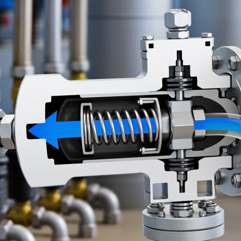
A pressure regulator reduces a higher inlet pressure to a steadier outlet pressure. Inside, a spring pushes on a flexible diaphragm, which senses pressure downstream. An adjustment screw changes spring compression, setting the desired outlet pressure. More compression usually means a higher setpoint. That is the balance.
When outlet pressure falls, the diaphragm moves and allows the valve to open farther. More gas or liquid flows through, restoring downstream pressure. If outlet pressure rises, the diaphragm pushes back against the spring, and the valve restricts flow. The spring supplies force; the diaphragm translates pressure changes into movement. A small shift can matter.
Real regulators do not hold pressure perfectly. Flow demand, inlet pressure, friction, and diaphragm wear can all affect the result. Not perfectly, though. A regulator may show a slight pressure drop as flow increases, often called droop. For example, a workshop gauge might read near its setpoint with a closed tool, then dip when the tool starts drawing air. The exact response depends on the regulator’s design and operating range. Check the pressure with a suitable gauge under actual flow, and follow the equipment maker’s instructions. Spring force is only part of the story.
What Is a Pressure Regulator and How Does It Work?
Spring-and-diaphragm force balance controls outlet pressure.
This illustrative chart assumes a 10 cm² effective diaphragm area and a 300 N spring force at a fixed diaphragm position. Outlet pressure produces an opposing diaphragm force; the forces balance at about 3 bar (300 kPa). If outlet pressure falls, spring force moves the diaphragm to open the valve; if pressure rises, diaphragm force moves it toward closing. In a real regulator, spring force changes slightly with diaphragm movement, so the set pressure may vary.
Direct-Acting and Pilot-Operated Designs: Flow and Response Differences
A pressure regulator reduces a higher inlet pressure and maintains a steadier outlet pressure as conditions change. In a direct-acting design, downstream pressure pushes against a diaphragm or piston, while a spring pushes in the opposite direction. When outlet pressure falls, the spring opens the valve; as pressure rises, the valve closes. It is a simple, compact arrangement. It can respond quickly, but outlet pressure may sag as flow demand increases.
A pilot-operated regulator uses a smaller pilot valve to control pressure above or around the main valve diaphragm. That pressure helps move the larger valve, allowing the regulator to handle higher flow with more stable outlet pressure. This design is often useful where demand changes sharply, such as when several process lines draw gas at once. The extra control stage can make response slower, though actual performance depends on the regulator and installation. Neither design is automatically better.
Tips: Check the regulator’s flow range, not just its pipe size. Watch the outlet gauge while demand changes; a brief pressure drop can reveal droop. Keep sensing lines clear and follow the manufacturer’s setup guidance. One detail is easy to overlook: a steady reading at low flow does not prove the regulator will behave the same under peak demand.
Regulator Sizing with Cv: Water Flow at a 1 psi Pressure Drop
A pressure regulator reduces a higher inlet pressure and holds a chosen downstream pressure as demand changes. For water-flow sizing, Cv offers a useful starting point: it represents flow in US gallons per minute through a valve with a 1 psi pressure drop, under specified reference conditions. It is not a promise of actual regulator performance.
For water near 60°F, specific gravity is approximately 1. The ISA/IEC 60534-2-1:2011 flow-capacity standard uses the liquid relationship Q = Cv × square root of (pressure drop divided by specific gravity). At a 1 psi drop, the estimate becomes simple: a Cv of 2 corresponds to about 2 gallons per minute. The math is simple. Picture a steady stream filling a marked bucket; the estimate describes that flow, not the outlet pressure during changing demand.
Real regulators can behave differently. Inlet pressure, set pressure, seat design, and flow demand affect capacity and pressure droop. A regulator delivering 2 gallons per minute may need more than a 1 psi pressure drop to maintain its setpoint. Check the regulator’s published capacity curves at the actual inlet and outlet pressures, then allow for operating variation. Cv alone can make sizing look more certain than it is. For critical service, confirm the selection against the manufacturer’s performance data and qualified engineering review.
Selecting a Regulator: Verify Inlet Rating, Setpoint, and Capacity
A pressure regulator reduces a higher inlet pressure to a controlled downstream pressure.
For selection, check the maximum inlet rating against the highest pressure the system can actually deliver, including startup spikes. The regulator’s body and connections must also suit the gas or liquid, temperature, and operating conditions. Check the nameplate.
A safe-looking normal reading does not confirm that the regulator can handle a brief pressure surge.
Set the outlet setpoint to match the equipment’s required pressure, then verify it with a gauge while the system is flowing. Many regulators show some pressure drop as demand rises; a static reading alone can hide this.
Capacity matters just as much. Compare the required flow rate with the regulator’s published flow data at your inlet pressure and setpoint, rather than choosing by pipe size alone.
Small details matter. Consider peak demand, such as several tools starting together, and leave reasonable operating margin.
Oversizing is not automatically safer: a regulator that is too large may control poorly at low flow.
Recheck the choice if the supply pressure or demand changes; those assumptions are easy to miss.

 More