
 More
More 
Choosing the right Resonant Capacitors can determine whether a power converter runs quietly or overheats under load. The decision involves more than matching a capacitance value. Engineers must examine voltage stress, operating frequency, equivalent series resistance, ripple current, and thermal behavior. Small errors become expensive.
A capacitor rated for 450 volts may still fail in a demanding resonant circuit. Switching spikes can exceed the expected waveform. Heat can also reduce service life when airflow is limited. Film capacitors, especially polypropylene types, often suit high-frequency applications because they offer low losses and stable electrical performance. However, every design has different priorities. Size, cost, mounting space, and expected operating hours matter.
Reliable selection begins with the circuit’s measured conditions. Record the actual frequency, peak voltage, RMS current, and ambient temperature. Then compare these values with the manufacturer’s detailed specifications, not only the product headline. Look for dissipation factor, self-resonant behavior, insulation requirements, and permissible pulse performance. Testing matters.
A simulation may predict excellent results. Real hardware can disagree. Layout inductance, cooling limits, and production tolerances can change the outcome. This is where careful prototypes and temperature measurements provide useful evidence. Designers should also review recognized industry standards and obtain traceable supplier documentation. A lower-cost capacitor may appear attractive, but premature drift can increase maintenance costs. The perfect choice is rarely obvious. It requires judgment, verification, and a willingness to question convenient assumptions.
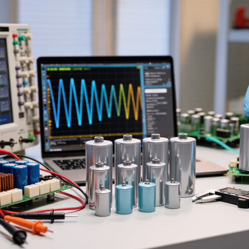
How to Choose the Right Resonant Capacitors?
Resonant capacitors shape energy transfer between inductors and switching devices. Their value sets the resonant frequency, usually calculated as fr = 1/(2π√LC). A small capacitance error can shift this point. That shift may increase switching loss, acoustic noise, or device stress. In an LLC converter, I check capacitance, voltage rating, ESR, and ripple current together. One number never tells the whole story.
The capacitor must tolerate repeated AC pulses, not only its stated DC voltage. Film capacitors often suit high-frequency resonant tanks because they offer low loss and stable capacitance. Ceramic parts can work well at compact dimensions, but voltage bias and mechanical cracking require attention. According to MarketsandMarkets’ Power Electronics Market report (2024), demand for efficient conversion systems is expanding across electric mobility and renewable infrastructure. Thermal margins matter more in those environments. They are not optional.
I measure the tank at operating temperature, then compare actual frequency with the design model. The model can lie. Stray inductance from copper tracks and terminals changes the result, sometimes noticeably above 100 kHz. The IEA Electricity 2024 report forecasts strong global electricity-demand growth through 2026, increasing pressure on converter efficiency. I would therefore select a capacitor with credible lifetime data, controlled tolerance, and enough ripple-current headroom. A cheaper part may pass the bench test, yet fail after months of heat cycling. That possibility deserves deliberate review.
Typical engineering characteristics for selecting capacitors in resonant, filtering, matching, and power-conversion circuits
| Capacitor Type | Typical Capacitance Range | Typical Frequency Suitability | Typical Tolerance | Temperature Behavior | Key Strength | Important Limitation |
|---|---|---|---|---|---|---|
| C0G/NP0 Ceramic | Approximately 1 pF to 100 nF | High-frequency RF, MHz to GHz applications | Typically ±0.1% to ±5% | Very stable; approximately 0 ±30 ppm/°C | Very low loss, low dielectric absorption, and excellent frequency stability | Limited capacitance and energy storage compared with other dielectric types |
| X7R Ceramic | Approximately 1 nF to 10 µF | From low frequency to several MHz, depending on size and construction | Typically ±5% to ±20% | Rated operating range approximately −55°C to +125°C; capacitance changes with DC bias | Compact size, high volumetric capacitance, and low cost | DC-bias derating, aging, piezoelectric effects, and higher loss than C0G/NP0 |
| Polypropylene Film | Approximately 1 nF to 100 µF | Audio, power electronics, induction heating, and resonant converters from Hz to hundreds of kHz | Typically ±2% to ±10% | Low dielectric loss and good long-term stability; temperature coefficient commonly around ±200 ppm/°C | High pulse-current capability, low ESR, and low dielectric absorption | Larger physical size and lower capacitance per volume than ceramic capacitors |
| Polyester Film | Approximately 1 nF to 10 µF | General-purpose filtering and lower-power resonant networks, typically below several hundred kHz | Typically ±5% to ±20% | Moderate stability; capacitance varies more with temperature than polypropylene | Good mechanical durability and economical film construction | Higher dielectric loss and lower high-frequency performance than polypropylene |
| Silver Mica | Approximately 1 pF to 10 nF | Stable RF oscillators, filters, and tuned circuits from kHz to hundreds of MHz | Typically ±1% to ±5% | Very stable with low aging and low temperature coefficient | High Q factor and excellent dimensional stability | Limited capacitance range and generally larger or more expensive than multilayer ceramics |
| Aluminum Electrolytic | Approximately 1 µF to several thousand µF | Low-frequency energy storage and ripple filtering; generally unsuitable for high-Q resonant operation | Typically ±20% | Capacitance, leakage current, and ESR vary significantly with temperature, frequency, and age | High capacitance at relatively low cost | Higher ESR, polarity requirement, leakage current, and limited ripple performance at high frequency |
| Design Parameter | Why It Matters | Recommended Design Check | Practical Guideline |
|---|---|---|---|
| Resonant Frequency | The capacitor works with the inductor to establish the circuit's resonant point. | Use fr = 1/(2π√LC). | Include capacitor tolerance, inductor tolerance, parasitic inductance, and operating temperature in the frequency calculation. |
| Voltage Rating | Resonant circuits can generate voltage magnification and repetitive peak stress. | Compare the rated voltage with the maximum RMS and peak voltage across the capacitor. | Use an appropriate engineering margin after considering transients, tolerance, and temperature derating. |
| RMS Current and Ripple Current | Current flowing through ESR produces heat and can shorten service life. | Verify the capacitor's RMS current rating at the actual frequency and ambient temperature. | For high-current resonant power stages, favor low-loss film or suitable high-frequency ceramic capacitors. |
| ESR and Dissipation Factor | Losses reduce circuit Q and increase self-heating. | Estimate power loss using P ≈ IRMS2 × ESR. | Select a capacitor with sufficiently low impedance at the operating frequency, not only at 1 kHz. |
| Capacitance Stability | Capacitance drift changes the resonant frequency and impedance. | Check temperature coefficient, DC-bias effect, aging, and applied-voltage dependence. | Use C0G/NP0 or film capacitors when frequency stability is critical. |
| Self-Resonant Frequency | Above its self-resonant frequency, a capacitor behaves increasingly inductively rather than capacitively. | Confirm that the intended operating frequency is sufficiently below the capacitor's self-resonant frequency. | Review the complete component layout because PCB traces, leads, and mounting introduce additional parasitic inductance. |
Note: The values shown are representative engineering ranges. Final selection should be verified against the capacitor manufacturer's electrical, thermal, frequency, pulse-current, and lifetime specifications for the intended circuit.